InnoDisk Matador II uses the PCIe interface, and it is compliant with PCIe
specification ver. 1.1 and can work with PCIe Gen. 1 X8 or above host system,
which is used in server computer. InnoDisk Matador II is compliant with PCIe Gen
1 specification (Gen 1 supports 2.5Gbps per lan data rate). A standard PCIe X8
edge-finger definition is used on Matador II. PCI Express is a serial interface.
A PCI Express link is the physical connection of two PCI Express devices. A PCI
Express lane contains both the transmit and receive signal pairs in a link. An
x1 link contains one PCI Express lane, whereas an x8 link contains eight PCI
Express lanes. The Raid controller supports x8 links. The PCI Express interface
expands upon and adds to the features offered in conventional PCI. More
information on any of these features is available in the PCI Express
specification.
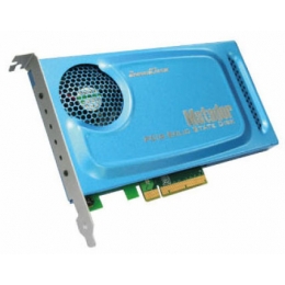
Matador II form factor Matador II form factor design with metal material case is
easy for installation because PCIe is a popular form factor. InnoDisk Matador II
has a compact design with the dimension of 171.25 mm x 89.30 mm x 17.90 mm.
InnoDisk Matador II provides unformatted 64GB, 128GB and 256GB capacities within
SLC flash ICs and 128GB, 256GB and 512GB capacities within MLC flash ICs
 |
Operating Temperature Range:Standard Grade: 00C to +700C
(available currently)
Industrial Grade: -400C to +850C(under development)
Storage Temperature Range: Standard Grade: -550C to +950C
Industrial Grade: -550C to +950C
Relative Humidity: 10-95% , Non-Condensing |
 |
|
|
Reliability |
Test Conditions |
| Without Package |
Vibration |
5 Hz to 500Hz, 2G, 3 axes |
| Mechanical Shock |
Duration: 6ms, 100G, 3 Axes |
| With Package |
Drop |
96cm |
| Vibration |
1.14G rms, 1-800Hz |
| Product |
Condition |
MTBF(Hours) |
| InnoDisk Matador II PCIe SSD |
TELECORDIA SR-332 GB, 250C |
>4,000,000 |
|
 |
InnoDisk Matador II PCIe SSD support following transfer mode: PCIe Gen. 1
X8
|
 |
| Sequential read: |
SLC: 910MB/s |
| MLC: 700MB/s |
| Sequential write: |
SLC: 750MB/s |
| MLC: 530MB/s |
| Random read: |
450MB/s (Test By Everest) |
| Random Write: |
350MB/s (Test By Everest) |
|
 |
Flash memory can be erased within a limited number of times. This number is
called the erase cycle limit or write endurance limit and is defined by the
flash array vendor. The erase cycle limit applies to each individual erase block
in the flash device. InnoDisk Matador II uses a static wear-leveling algorithm
to ensure that consecutive writes of a specific sector are not written
physically to the same page/block in the flash. This spreads flash media usage
evenly across all pages, thereby extending flash lifetime. |
Bad Blocks are blocks that contain one or more invalid bits whose
reliability are not guaranteed. The Bad Blocks may be presented while the SSD is
shipped, or may develop during the life time of the SSD. The Bad Blocks will not
exceed more than 6.7% of the total device volume. When the Bad Blocks is
detected, it will be flagged, and not be used anymore. The SSD implement Bad
Blocks management, Bad Blocks replacement, Error Correct Code to avoid data
error occurred. The functions will be enabled automatically to transfer data
from Bad Blocks to spare blocks, and correct error bit. After the reserved block
under 40, the SSD will be locked, and the SSD cannot be written anymore. Host
can send a vendor ATA command to unlock the SSD for backup data or system from
SSD.
|